
Introduction
Boring, I’ll add something with lots of buzz words later so all the SEO people can jerk off on it.
MIDI Basics & Wiring
The MIDI Association defines how to wire up a serial MIDI transmitter:
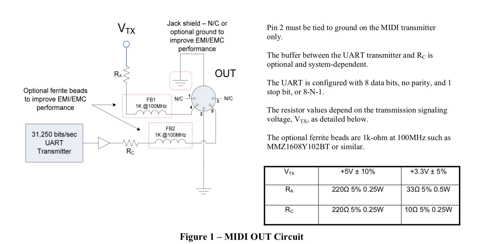
Source: https://www.midi.org/specifications-old/item/midi-din-electrical-specification
It’s fairly straight forward, UART TX via Rc to pin 5, ground to pin 2 and Vtx via Rc to pin 4 of the good ol’ 5-pin DIN connector we all know and "love". Easy, right?
But what’s that element in between UART and Rc? Well, that’s a curveball I stumbled across and many schematics online depict it differently.
When I wired everything up without it and conducted my first tests with one device as a MIDI receiver, everything worked fine. With a second device, it didn’t, so I dug deeper.
Most schematics online depict two logical NOTs (inverters) in series. That doesn’t make any sense, does it? Logically, it doesn’t, because the binary signal coming out will be the same that has been put in.
But it does something to the level, i.e. HIGH. The HIGH levels coming out of most micro controllers, like the Raspberry Pi Zero 2 (at least in my case) has a HIGH of 3.3V.
However, depending on the MIDI standard of the receiver, it might expect HIGH to be 5V. In my case, device 1 was fine with 3.3V, device 2 needed 5V and basically ignored any messages being sent with 3.3V as HIGH.
I found out that most articles online recommend a 7404 hex inverter. Apart from being an inverter, that chip also acts as a buffer setting high to a stable 5V, whether you feed it with 3.3V or 5V.
That’s pretty neat. As soon as I got one of those, everything worked fine with both my devices.
Here’s the final breadboard wiring I ended up with:
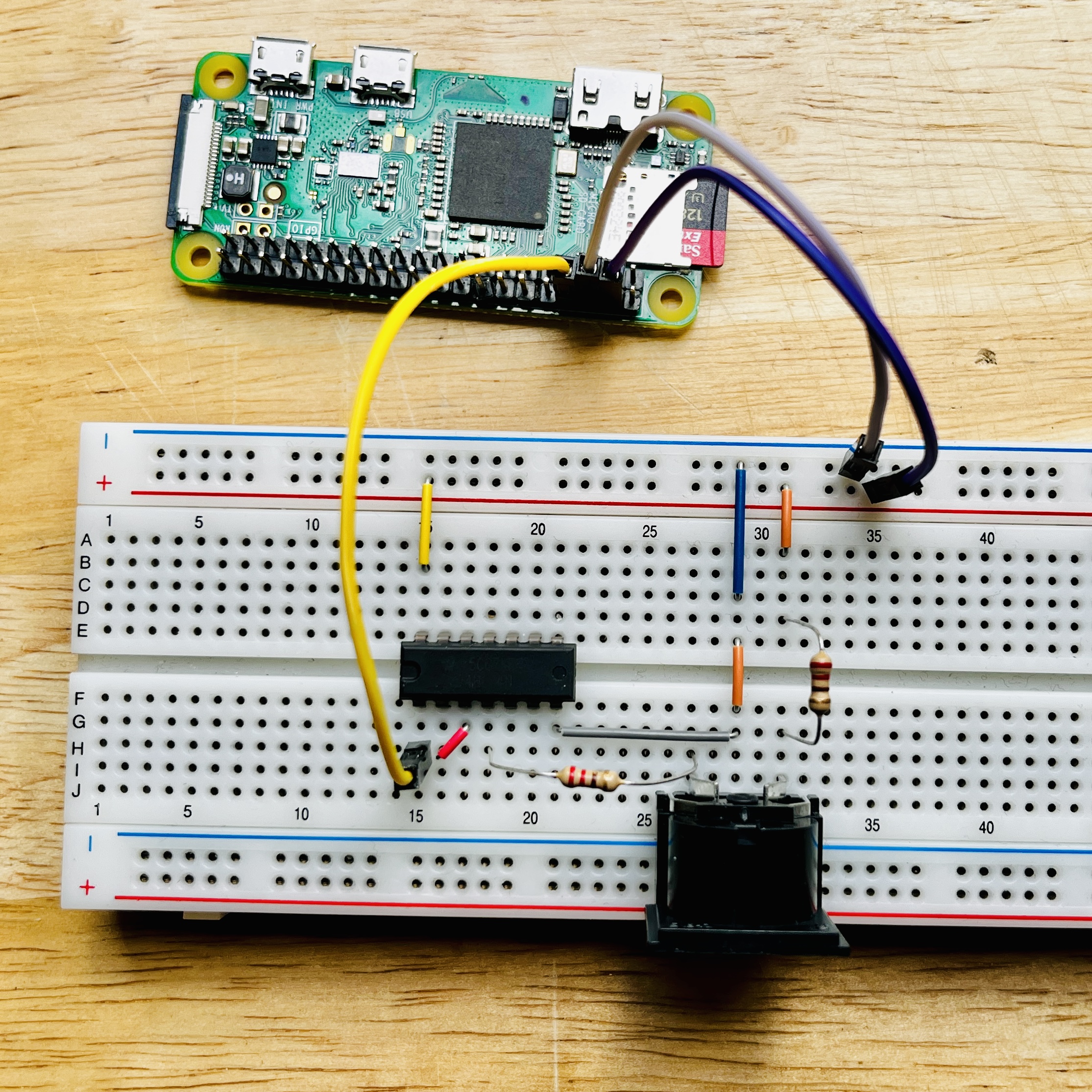
- I used 220 Ohms for Rc
- I tried both the 74HC04 and the 7404N from TI as hex inverters and both worked fine
- UART TX is GPIO 14 (pin 8) on the RPi (yellow)
- Note how the UART TX (yellow) goes into the first NOT gate and its output straight into the next (red). The output of the second NOT goes to the DIN connector via 220Ohms
- Note that this wiring is the same for both RPi and Arduino, the pins are different ones. Arduino has the UART pins marked as RX/TX.
Sending MIDI messages with python
Sending a MIDI message over serial is as easy as this:
#!/usr/bin/env python3

import serial

ser = serial.Serial("/dev/serial0", 31250)
ser.write(b'\xb0\x2c\x00')
Where
- the first nibble (0xB, 1011) defines the message type, which is a control change message (CC) in this case
- the second nibble (0x0, 0000) defines the MIDI channel, where 0 refers to the first channel
- the 2nd and 3rd bytes are data bytes usually specified by the device that’s being controlled – in this case the 0x2c (44) is a BPM tap tempo message where the value (0x00) is irrelevant
(Also See https://midi.org/summary-of-midi-1-0-messages)
Notes on UART
On newer RPi models, the default serial port (/dev/serial0) links to the miniUART (/dev/ttyS0).
However, if you need more speed or more reliable timing, you might prefer the actual SoC serial interface (/dev/ttyAMA0).
However, the AMA0 might be used by bluetooth, which is why disabling bt via config might be necessary:
dtoverlay=miniuart-bt