Introduction
Recently, I’ve been experimenting with treble bleed circuits on my Fender custom shop strat that has 3 single coils. Everything you will find here is based on this website and I want to document my personal learnings/findings.
What is a treble bleed?
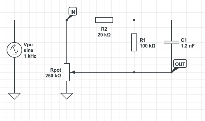
Usually, whenever you dial down the volume pot on your single coil guitar, high frequencies will be attenuated. This is because the pickups, the cable and the resistance of the volume pot together form a passive filter. This “filter” changes its characteristics dependant on how much resistance is added by the volume pot. A “treble bleed” is an additional passive filter, a high-pass filter to be more precise, that can be added in parallel to the volume pot and the output of the guitar. This will preserve high frequency content as the player rolls down the volume pot. As stated in the linked article above, there are many variants of those treble bleeds. I will only address the Fender way in this article, i.e. two resistors, one capacitor:
What does a treble bleed look like?
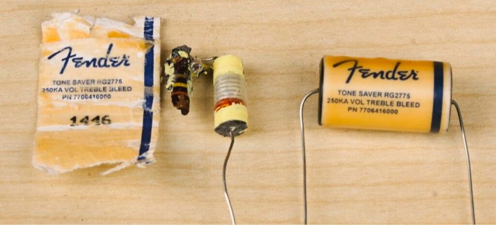
There are basically three designs of treble bleeds: The Fender tone-saver approach, which is an encapsulated two wire “shell” that contains all the components. Fender sells those for lots of money even though the contained components are fairly cheap.
Newer strats like my American Professional II come with a printed circuit board (PCB) and surface mounted devices (SMD):

Then, there’s the DIY approach, which basically consists of soldering the three cheap components together manually.

Please don’t let all the cork sniffers fool you. You can get along with the cheapest resistors and capacitors you can find. A treble bleed shouldn’t cost you more than 5 bucks.
Which values do I need?
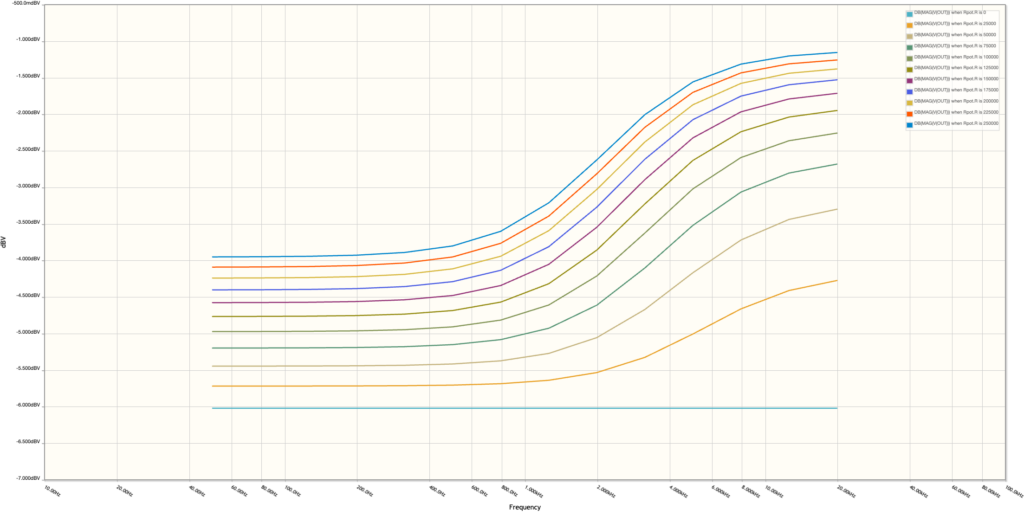
Well, this is where things get a little cloudy. If you ask 5 different sources, you’ll end up with 6 different sets of values. The blog mentioned above suggests to use R1=150k, R2=20k and C1=1.2nF. This was also my first attempt and I liked it. However, when I changed strings on my Am. Prof. II strat, I measured the values on the PCB and they’re R1=100k, R2=20k and C1=1.2nF. So, R1 has a different value. So I decided to simulate the differences between those two values:
R1 = 150k, R2 = 20k, C1 = 1.2nF
R1 = 100k, R2 = 20k, C1 = 1.2nF
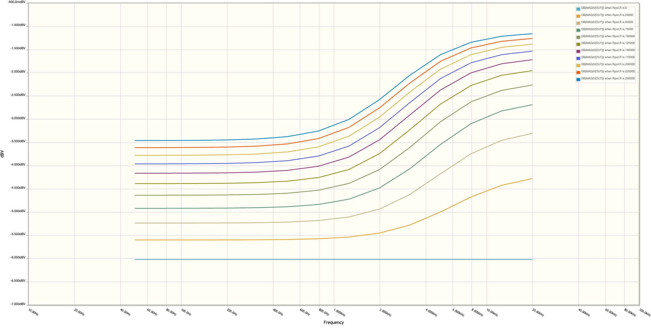
It seems to me that R1=100k is more subtle.
Note that the bottom graph represents 0 resistance at the pot, i.e. the pot being fully open.
